Planning Your Own Hydro System
Bookmark this page (Ctrl+D)
![]() View/Print PDF Version
View/Print PDF Version
Guide Navigation
Measuring Flow
The Most Accurate Method for Measuring Flow
Method 3: Measuring with a Weir
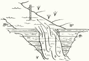
A Weir is perhaps the most accurate way to measure small and medium sized streams. All the water is directed through an area that is exactly rectangular, making it very easy to measure the height and width of the water to compute FLOW.


A Weir is a temporary dam with a rectangular slot, or Gate. The bottom of the Gate should be exactly level, and the width of the Gate should allow all the water to pass through without spilling over the top of the dam. A narrower Gate will increase the depth of the water as it passes through, making it easier to measure.
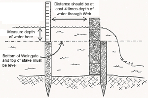
It’s important to note that your depth measurement is not taken at the gate itself because the water depth distorts as it moves through the gate. Instead, insert a stake well upstream of the Weir gate and make the top of the stake exactly level with the bottom of the Wier gate. Measure the depth of the water from the top of the stake.
Once the width and depth of the water are known, a Weir Table is used to compute the flow. The Weir Table shown below is based on a Gate one inch wide; you simply multiply the table amount by the width (in inches) of your Gate. For example, let’s assume your Weir Gate is 6” wide, and the depth of the water passing over it is 7-1/2 inches. On the left side of the table, find “7” and move across the row until you find the column for “+1/2”. The table shows 8.21 cfm flow for a one-inch Gate with 7-1/2” of water flowing through it. Since your gate is 6” wide, simply multiply the 8.21 by 6 to get 49.26 cfm.
|
Inches |
||||||||
|
|
+0/8 |
+1/8 |
+1/4 |
+3/8 |
+1/2 |
+5/8 |
+3/4 |
+7/8 |
|
0 |
0.00 |
0.01 |
0.05 |
0.09 |
0.14 |
0.19 |
0.26 |
0.32 |
|
1 |
0.40 |
0.47 |
0.55 |
0.64 |
0.73 |
0.82 |
0.92 |
1.02 |
|
2 |
1.13 |
1.23 |
1.35 |
1.46 |
1.58 |
1.70 |
1.82 |
1.95 |
|
3 |
2.07 |
2.21 |
2.34 |
2.48 |
2.61 |
2.76 |
2.90 |
3.05 |
|
4 |
3.20 |
3.35 |
3.50 |
3.66 |
3.81 |
3.97 |
4.14 |
4.30 |
|
5 |
4.47 |
4.64 |
4.81 |
4.98 |
5.15 |
5.33 |
5.51 |
5.69 |
|
6 |
5.87 |
6.06 |
6.25 |
6.44 |
6.62 |
6.82 |
7.01 |
7.21 |
|
7 |
7.40 |
7.60 |
7.80 |
8.01 |
8.21 |
8.42 |
8.63 |
8.83 |
|
8 |
9.05 |
9.26 |
9.47 |
9.69 |
9.91 |
10.13 |
10.35 |
10.57 |
|
9 |
10.80 |
11.02 |
11.25 |
11.48 |
11.71 |
11.94 |
12.17 |
12.41 |
|
10 |
12.64 |
12.88 |
13.12 |
13.36 |
13.6 |
13.85 |
14.09 |
14.34 |
|
11 |
14.59 |
14.84 |
15.09 |
15.34 |
15.59 |
15.85 |
16.11 |
16.36 |
|
12 |
16.62 |
16.88 |
17.15 |
17.41 |
17.67 |
17.94 |
18.21 |
18.47 |
|
13 |
18.74 |
19.01 |
19.29 |
19.56 |
19.84 |
20.11 |
20.39 |
20.67 |
|
14 |
20.95 |
21.23 |
21.51 |
21.80 |
22.08 |
22.37 |
22.65 |
22.94 |
|
15 |
23.23 |
23.52 |
23.82 |
24.11 |
24.40 |
24.70 |
25.00 |
25.30 |
|
16 |
25.60 |
25.90 |
26.20 |
26.50 |
26.80 |
27.11 |
27.42 |
27.72 |
|
17 |
28.03 |
28.34 |
28.65 |
28.97 |
29.28 |
29.59 |
29.91 |
30.22 |
|
18 |
30.54 |
30.86 |
31.18 |
31.50 |
31.82 |
32.15 |
32.47 |
32.80 |
|
19 |
33.12 |
33.45 |
33.78 |
34.11 |
34.44 |
34.77 |
35.10 |
35.44 |
|
20 |
35.77 |
36.11 |
36.45 |
36.78 |
37.12 |
37.46 |
37.80 |
38.15 |
A Weir is especially effective for measuring FLOW during different times of the year. Once the Weir is in place, it is easy to quickly measure the depth of the water and chart FLOW at various points in time.
Design Flow
Even though your Flow may be very high after exceptionally rainy periods, it probably won’t be cost effective to design your turbine system to handle all that water for just a few days of the year. Instead, it makes sense to build a system that uses Flow you can count on for much of the year. This is called Design Flow, and it is the maximum Flow your hydro system is designed to accommodate.
Design Flow, along with Net Head, determines everything about your hydro system, from pipeline size to power output.